148 Results
View results:
Sort by:

The three types of moment frames (Ordinary, Intermediate, Special) are available in the Steel Design add-on of RFEM 6. The seismic design result according to AISC 341-22 is categorized into two sections: member requirements and connection requirements.

The National Building Code of Canada (NBC) 2020 Article 4.1.8.7 provides a clear procedure for earthquake methods of analysis. The more advanced method, the Dynamic Analysis Procedure in Article 4.1.8.12, should be used for all structure types except those that meet the criteria set forth in 4.1.8.7. The more simplistic method, the Equivalent Static Force Procedure (ESFP) in Article 4.1.8.11, can be used for all other structures.

RWIND 2 and RFEM 6 can now be used to calculate wind loads from experimentally measured wind pressures on surfaces. Basically, two interpolation methods are available to distribute pressures measured in isolated points across the surfaces. The desired pressure distribution can be achieved using the appropriate method and parameter settings.

The Steel Design add-on in RFEM 6 now offers the ability to perform seismic design according to AISC 341-16 and AISC 341-22. Five types of seismic force-resisting systems (SFRS) are currently available.

The three types of moment frames (Ordinary, Intermediate, Special) are available in the Steel Design add-on of RFEM 6. The seismic design result according to AISC 341-16 is categorized into two sections: member requirements and connection requirements.

If you want to use a pure surface model, for example, when determining the internal forces and moments, but the structural component is still designed on the member model, you can take advantage of a result beam.

In RFEM 6, the results for the FE mesh nodes are determined using the finite element method. For the distribution of internal forces, deformations, and stresses to be continuous, these nodal values are smoothed through an interpolation process. This article will introduce and compare the different types of smoothing that you can use for this purpose.

Surfaces in building models can be of many different sizes and shapes. All surfaces can be considered in RFEM 6 because the program allows to define different materials and thicknesses as well as surfaces with different stiffness and geometry types. This article focuses on four of these surface types: rotated, trimmed, without thickness, and load transfer.

In computational fluid dynamics (CFD), complex surfaces that are not completely solid can be modeled using porous or permeability media. In the actual world, examples of such things include windbreak fabric structures, wire meshes, perforated facades and claddings, louvers, tube banks (stacks of horizontal cylinders), and so on.

Line releases are special objects in RFEM 6 that allow structural decoupling of objects connected to a line. They are mostly used to decouple two surfaces that are not rigidly connected or transferring only compressive forces at the common boundary line. By defining a line release, a new line is generated at the same place which transfers only the locked degrees of freedom. This article will show the definition of line releases in a practical example.

Windbreak structures are special types of fabric structures which protect the environment from harmful chemical particles, abate wind erosion, and help to maintain valuable sources. RFEM and RWIND are used for wind-structure analysis as one-way fluid-structure interaction (FSI).
This article demonstrates how to structural design windbreak structures using RFEM and RWIND.
RWIND 2 is a program for generating wind loads based on CFD (Computational Fluid Dynamics). The wind flow numerical simulation is generated around any building, including irregular or unique geometry types, to determine the wind loads on surfaces and members. RWIND 2 can be integrated with RFEM/RSTAB for the structural analysis and design or as a stand-alone application.

In RFEM 6 it is possible to define multilayer surface structures with the help of the “Multilayer Surfaces” add-on. Hence, if you have activated the add-on in the model’s Base Data, it is possible to define layer structures of any material model. You can also combine material models of, for example, isotropic and orthotropic materials.

This article shows you how to create contacts between two or more parallel surfaces by controlling the transfer of forces between them.

This article will show you how to properly consider the connection between surfaces that touch each other on one line with the help of line hinges in RFEM 6.

This article shows you how to define different types of member transverse stiffeners in RFEM 6 and RSTAB 9. It also shows you how to consider them in the design as well as the calculation of members with 7 degrees of freedom.
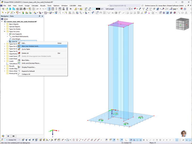
In RFEM 6, it is possible to define line welds between surfaces and calculate the weld stresses using the Stress-Strain Analysis add-on. This article will show you how to do it.

RWIND 2 is a program for generating wind loads based on CFD (Computational Fluid Dynamics). The wind flow numerical simulation is generated around any building, including irregular or unique geometry types, to determine the wind loads on surfaces and members. RWIND 2 can be integrated with RFEM/RSTAB for the structural analysis and design or as a stand-alone application.

In RFEM 6 it is possible to save selected objects (as well as whole structures) as blocks and reuse them in other models. Three types of blocks can be distinguished: non-parameterized, parameterized, and dynamic blocks (via JavaScript). This article will focus on the first block type (non-parameterized).

In accordance with Sect. 6.6.3.1.1 and Clause 10.14.1.2 of ACI 318-19 and CSA A23.3-19, respectively, RFEM effectively takes into consideration concrete member and surface stiffness reduction for various element types. Available selection types include cracked and uncracked walls, flat plates and slabs, beams, and columns. The multiplier factors available within the program are taken directly from Table 6.6.3.1.1(a) and Table 10.14.1.2.
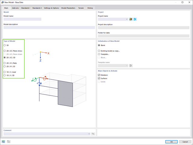
Structures are three-dimensional in reality; however, they can be simplified and analyzed as 2D or 1D models. The model type has a crucial influence on how the structural components are stressed, and it should be defined prior to modeling and calculation.

This article explains the use of surfaces with the Load Transfer stiffness type in RFEM 6. A practical example is also provided to demonstrate the application of self-weight, snow load, and wind load to a steel hall.

In order to create a surface model with failing supports close to reality, an option called "Failure if contact perpendicular to surfaces failed" is available in RFEM 5 for contact solids under "Contact Parallel to Surfaces".

In RFEM and RSTAB, there are various options to renumber the individual structural elements, such as nodes, lines, members, surfaces, or solids. Two options are available for renumbering: singly and automatically.

In RFEM, it is possible to display the resultant of a section or release. This article explains which part of the sectional area is affected. The easiest way would be to refer the resultant to a cut face of the surface. However, since a section may run through several surfaces with different local coordinate systems, determination by means of a cut face is not possible.

In RFEM 5 as well as RSTAB 8 in RF-/FOUNDATION Pro, you can save the foundation dimensions for all five foundation types as foundation templates in a user-defined database and use them later in other models.
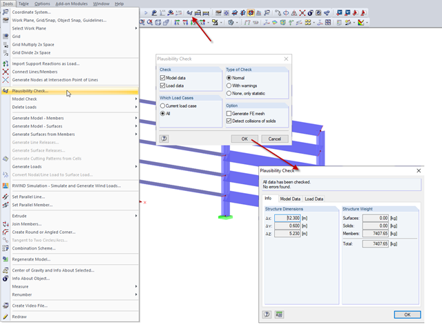
In RFEM and RSTAB, you can check the plausibility of entries before you start the calculation. This is done using "Tools" → "Check Plausibility ..." or the corresponding button in the toolbar. There are three different types of checks available.

In RFEM, you can display the contact properties between two surfaces by means of contact solids. Among other things, you should ensure that both contact surfaces of a contact solid have the same integrated objects. Therefore, when modeling the contact surfaces, we recommend using the copy function in order to create the second contact surface.

In RFEM, you can display the contact properties between two surfaces by means of contact solids.

You can make various settings in order to achieve a clearly‑arranged display of the result values. For example, some users may not want the white background in text bubbles. You can adjust the background in "Display Properties" using the Transparent and Background color option.